


Carbon fan blades

Thread Starter
Join Date: Dec 2007
Location: Montreal
Age: 92
Posts: 156
Likes: 0
Received 0 Likes
on
0 Posts
Carbon fan blades
Are there any carbon fibre fan blades in use in modern engines ? If so,
how are they protected from disintegration when hit by an object ?
I seem to have read somewhere that a new P&W design incorporates them,
if that is true.
how are they protected from disintegration when hit by an object ?
I seem to have read somewhere that a new P&W design incorporates them,
if that is true.

Yup.
General Electric GE90

Carbon fibre blades with Titanium leading and trailing edges.
General Electric GE90
Carbon fibre blades with Titanium leading and trailing edges.
Last edited by TURIN; 5th Nov 2012 at 20:10.
I seem to have read somewhere that a new P&W design incorporates them.
http://www.pprune.org/tech-log/49925...ew-engine.html
if that is true.

Thread Starter
Join Date: Dec 2007
Location: Montreal
Age: 92
Posts: 156
Likes: 0
Received 0 Likes
on
0 Posts
Carbon fan blades
Thanks everyone for your info. I was with RR when the proverbial sh't hit the fan and I lost my job as a result (RB211/Lockheed L-1011 lawsuit). Therefore, I am very interested in what solutions are being discovered to reduce (I don't think I can use the word eliminate) the disintegration of a blade when hit by a big bird ! Is the titanium structural and able to contain the failure ?
Anyone has the stats on the failure rate of the GE carbon fan with titanium L/E ? What are the resultant secondary damages ?
Anyone has the stats on the failure rate of the GE carbon fan with titanium L/E ? What are the resultant secondary damages ?
how are they protected from disintegration when hit by an object ?
I suspect that the design approach is to let the blade disintegrate after a certain sized impact and then to contain the parts of the blade.
Join Date: Aug 2011
Location: Grassy Valley
Posts: 2,074
Likes: 0
Received 0 Likes
on
0 Posts
EEngr
Isn't the purpose of a flywheel to "store" energy? The purpose of a fan to "shed" it?
A lightweight rotor is not the goal in energy storage? I am curious as to why a light wheel is desirable for retaining energy?
A light fan is more responsive to changes in rpm, as well, is that not also a reason for CF?
Thread Starter
Join Date: Dec 2007
Location: Montreal
Age: 92
Posts: 156
Likes: 0
Received 0 Likes
on
0 Posts
Quote
I'm not a structural or propulsion engineer, but I did some work on carbon fiber energy storage flywheels some years ago. My understanding of the failure modes of carbon fiber is that it 'delaminates' and produces something akin to cotton candy. The resulting material is much easier to contain (within the flywheel housing or in the case of an engine, the cowling).
I suspect that the design approach is to let the blade disintegrate after a certain sized impact and then to contain the parts of the blade.
That makes sense and containment was indeed one purpose of the CF blades plus the reduced gyroscopic affect from the weight saving, but probably not in aerodynamic profile thickness.
I can see that a carbon flywheel could have been useful in an artificial horizon instrument before the arrival of solid state sensors and GPS. What other applications were there ?
Join Date: Dec 2010
Location: Middle America
Age: 84
Posts: 1,167
Likes: 0
Received 0 Likes
on
0 Posts
To answer some of the questions posed here with some background information:
1. When the GE90 engine was in the conceptual stage of design, composite fan blades were part of the design. The basis for this came from the GE36 engine experience, an engine which had composite propulsors.
2. Composite fan blades are very strong given the methodology of construction and the materials used. Two key reasons on the GE90 for going this way was weight savings (300 lbs. per engine) and freedom of aerodynamic design. The "swept wing" aerodynamic design permits more air to be drawn into the engine producing added thrust. At the time, there wasn't a capable titanium process to yield the shape that was desired. The fan blades are about 4 feet long.
3. The thin titanium shield around the fan blade leading edge is to prevent erosion, particularly from sand. There is no titanium shield required on the trailing edge.
4. As I stated above, the fan blades are very strong and resist damage due to impact better than titanium fan blades. The experience in service has been remarkably good in this respect. For a substantial operating time, no fan blades required removal for bird strikes until several aircraft experienced large bird strikes, i.e., 9 to 10 lb. birds where the fan blades required removal and repair. As the engines have aged, the main cause of removal for servicing involves tip erosion probably from shedding ice prior to TO. There is a required procedure to accomplish this and of course there can be fan unbalance and tip rubbing while the procedure is carried out.
5. The fan casing on the GE90 is perfectly capable of containment should a whole fan blade completely break off as demonstrated as part of the engine certification program.
6. On the GEnx and Leap engines, the fan casing metallic material has been replaced by a composite fan casing. Again, it saves engine weight while being extremely strong, resisting penetration by foreign objects and the tendency to want to turn oval under full power.
7. A lighter fan has several advantages, one of which is less required LPT blade stages which drives the fan and another being reduced pressure on shaft bearings and seals.
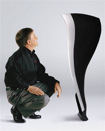
Below is a photo of a GE90 Fan blade. One of these is on display in the museum of modern art in NYC as an example of modern freeform design. I know of at least two fan blades being donated to charities for fund raising auction events.
TD
1. When the GE90 engine was in the conceptual stage of design, composite fan blades were part of the design. The basis for this came from the GE36 engine experience, an engine which had composite propulsors.
2. Composite fan blades are very strong given the methodology of construction and the materials used. Two key reasons on the GE90 for going this way was weight savings (300 lbs. per engine) and freedom of aerodynamic design. The "swept wing" aerodynamic design permits more air to be drawn into the engine producing added thrust. At the time, there wasn't a capable titanium process to yield the shape that was desired. The fan blades are about 4 feet long.
3. The thin titanium shield around the fan blade leading edge is to prevent erosion, particularly from sand. There is no titanium shield required on the trailing edge.
4. As I stated above, the fan blades are very strong and resist damage due to impact better than titanium fan blades. The experience in service has been remarkably good in this respect. For a substantial operating time, no fan blades required removal for bird strikes until several aircraft experienced large bird strikes, i.e., 9 to 10 lb. birds where the fan blades required removal and repair. As the engines have aged, the main cause of removal for servicing involves tip erosion probably from shedding ice prior to TO. There is a required procedure to accomplish this and of course there can be fan unbalance and tip rubbing while the procedure is carried out.
5. The fan casing on the GE90 is perfectly capable of containment should a whole fan blade completely break off as demonstrated as part of the engine certification program.
6. On the GEnx and Leap engines, the fan casing metallic material has been replaced by a composite fan casing. Again, it saves engine weight while being extremely strong, resisting penetration by foreign objects and the tendency to want to turn oval under full power.
7. A lighter fan has several advantages, one of which is less required LPT blade stages which drives the fan and another being reduced pressure on shaft bearings and seals.
Below is a photo of a GE90 Fan blade. One of these is on display in the museum of modern art in NYC as an example of modern freeform design. I know of at least two fan blades being donated to charities for fund raising auction events.
TD
Last edited by Turbine D; 8th Nov 2012 at 17:57. Reason: correct spelling

Join Date: Dec 2010
Location: Middle America
Age: 84
Posts: 1,167
Likes: 0
Received 0 Likes
on
0 Posts
msbbarratt,
Actually GE was interested in both. Since most of the thrust is developed by pushing air through the fan by-pass, the geometric shape of the composite fan blade increased by-pass flow, thus higher thrust. At the same time, less stages of LPT blades were required to drive the lighter fan, thus improving efficiency. In going from 76,000 lbs of thrust (early certified model) to 115,000 lbs of thrust, some architecture changes were made to engine components to increase fan speed, fan diameter, engine core speeds and turbine temperatures, but the number of LPT blade stages remained constant at 6 stages even with the larger fan blades on the GE90-115B.
TD
Is the point that GE weren't interested in greater thrust, just improved efficiency?
TD
I can see that a carbon flywheel could have been useful in an artificial horizon instrument before the arrival of solid state sensors and GPS. What other applications were there ?
The app I was working on was the use of flywheels in UPS/Static inverter systems.
Actually GE was interested in both. Since most of the thrust is developed by pushing air through the fan by-pass, the geometric shape of the composite fan blade increased by-pass flow, thus higher thrust. At the same time, less stages of LPT blades were required to drive the lighter fan,
Join Date: Aug 2011
Location: Grassy Valley
Posts: 2,074
Likes: 0
Received 0 Likes
on
0 Posts
The rotor mass is less, takes less energy to maintain its RPM, and the energy is more quickly translated into flow. I think the stress on the rotating machinery is less as N1 fluctuates, also.
Is the serpentine design to allow more blade length without adding diameter to the rotating disc? Less tip speed for given swept area?
Is the serpentine design to allow more blade length without adding diameter to the rotating disc? Less tip speed for given swept area?
Thread Starter
Join Date: Dec 2007
Location: Montreal
Age: 92
Posts: 156
Likes: 0
Received 0 Likes
on
0 Posts
Carbon Fan blades
Quote; Energy storage: Chrysler Patriot - Wikipedia, the free encyclopedia
Interesting. Also the reply about rotating mass etc. The inner fan portion compresses air into the LP compressor which makes this section more effective delivering air to the HP compressor. Am I right in this ?
Interesting. Also the reply about rotating mass etc.
The inner fan portion compresses air into the LP compressor which makes this section more effective delivering air to the HP compressor. Am I right in this ?
One problem with these blades , and the sheer size of the engine case has been tip rub . This meant a minor cropping to prevent this and reduced efficiency. The mention of the LPT is apt at the moment as that is this engines [115] achillies heel . Being replaced very regularly due to major failures and lots and lots of boroscope inspections ! The GE boys are keeping very very busy , but to be fair not many inflight failures due to the quality of the inspections and monitoring.
Join Date: Dec 2010
Location: Middle America
Age: 84
Posts: 1,167
Likes: 0
Received 0 Likes
on
0 Posts
lomapaseo,
The way I look at it is this (could be wrong): The function of the LPT is to extract energy from the core flowpath gas to provide torque to drive the fan and booster. Once the core engine is designed and tested by itself, the available energy becomes known. Then the LPT can be designed to extract only the energy necessary to drive the fan and booster to maximum speed plus a margin. A lighter fan and booster requires less torque than a heavier fan and booster. From then on it is up to the turbine aero and design folks to come up with the proper number of LPT stages required, less being better. The object is one of low weight, low cost and long life. To achieve these goals, the trend is towards higher stage loading with fewer stages. Sometimes it becomes a problem as bvcu points out in his posting, where design margins get too slim and the life goals are not met as predicted.
Lyman,
I believe this to be correct.
I don't know the answer to these.
TD
I can't get my head around the number of turbine stages being less becauses the fan weighs less for the same flow rate.
Lyman,
The rotor mass is less, takes less energy to maintain its RPM, and the energy is more quickly translated into flow.
Is the serpentine design to allow more blade length without adding diameter to the rotating disc? Less tip speed for given swept area?
TD