


Hypersonic Deltas


Thread Starter
Join Date: Dec 2010
Location: New York & California
Posts: 414
Likes: 0
Received 0 Likes
on
0 Posts
Hypersonic Deltas
Assuming it's not classified: Why have there been so many concepts for hypersonic planes that had highly swept delta wings? Wouldn't the shockwave be swept behind the wing, thus producing a large increase in drag and a large center of pressure shift?

this is another involved explanation I would suggests a Google search of the following....'oblique and normal shock waves' and Prandtl-Meyer Expansion wave phenomena...
because the shock wave dissipates energy upon adiabatic expansion as long as the airframe is substantially within the mach cone.
Also, it depends on whether it's a double wedge- blunt object-like a bullet or a sharp object like an arrow...however the delta wing is the best planform for mitigation of compressibility effects as around 45 degrees the maximum reduction of normal sensed true airspeed vector occurs according to the Cosine of the sweep angle. of course, the basic airfoil shape is always important, thereby alleviating drag rise with TAS increase as well as compressibility effects...one other the most difficult aspects of high speed design is the heat dissipation problems associated with ram rise
the two basic designs would either be a Double wedged or circular arc...as I had said it's a very involved topic...
there are folks here more qualified in high speed aerodynamics than me so apologize for any horse hooey if any
Last edited by Pugilistic Animus; 1st May 2011 at 19:35.
Join Date: Nov 2010
Location: Beijing
Age: 30
Posts: 43
Likes: 0
Received 0 Likes
on
0 Posts
I was believe that the delta wing is the best shape that give a benefit in structure term and drag due to swept angle. However after I saw the graph below I'm not sure wat is going on that cause the delta wing to produce more drag than the straight wing.
Could somebody explain this to me please?

Best regards
Could somebody explain this to me please?
Best regards
Thread Starter
Join Date: Dec 2010
Location: New York & California
Posts: 414
Likes: 0
Received 0 Likes
on
0 Posts
Pugilistic Animus
Yeah but at Mach 5, and Mach 6 how far back is the mach cone swept? What if the airframe is not entirely inside the cone?
Mr. Vortex
As I interpret that image, a straight wing has a lower drag coefficient than the delta or swept wing....
the shock wave dissipates energy upon adiabatic expansion as long as the airframe is substantially within the mach cone.
Mr. Vortex
As I interpret that image, a straight wing has a lower drag coefficient than the delta or swept wing....
Aviator Extraordinaire
Join Date: May 2000
Location: Oklahoma City, Oklahoma USA
Age: 77
Posts: 2,394
Likes: 0
Received 0 Likes
on
0 Posts
For ultra high Mach flight, I'd suggest you look up Lifting Body aircraft.
Landing is not all that bad, but they need a hell of a lot of runway to takeoff.
But then again, the Space Shuttle is a delta wing and it certainly does ultra high Mach speed.
Landing is not all that bad, but they need a hell of a lot of runway to takeoff.
But then again, the Space Shuttle is a delta wing and it certainly does ultra high Mach speed.
Could somebody explain this to me please?
Yeah but at Mach 5, and Mach 6 how far back is the mach cone swept? What if the airframe is not entirely inside the cone?
Thread Starter
Join Date: Dec 2010
Location: New York & California
Posts: 414
Likes: 0
Received 0 Likes
on
0 Posts
Pugilistic Animus
If the leading edges are sharp, as I understand from what I read in books, the shockwave will sweep behind the leading edge of the wing. Drag rise from what I understand has to do with the shock wave passing through the whole leading edge (which is actually longer on a swept wing or delta wing than a straight wing) and from trim-drag due to the fact that on a straight wing while supersonic or swept wing at the same angle as the shockwave off it's wing-root, the center of pressure shifts back to the 50% chord position.
You mean pitch down tendency and low drag when getting through Mach 1?
Out of curiosity: Anybody heard of the Kuchemann Tau?

Basically the idea revolves around adding a sharp spatular insert (2D, sharp leading-edge) in between a delta winged wave-rider that is half the span of the delta-winged section. It effectively reduces drag considerably.
As I understand
1.) It would probably reduce supersonic drag as the shockwave is going to probably be behind the leading edge anyway, and a low-sweep has lower supersonic drag than a highly swept wing.
2.) It would probably make the inlet design simpler as it doesn't have to be wrapped around the curve as you have a 2D ramp over a 3D cone
Still, I'm wondering if a thin diamond shaped wing would be more suitable as that wing-shape works well when the shock-wave sweeps beyond the leading-edge of the wing with a spatular insert in the middle; or an ogival shape with the inboard section spatular with the sweep progressively increased from the root to the tip (like a shovel or certain mideval shields).
Just a guess but perhaps the drag rise is due to detached shock wave as the object becomes more blunted
the delta plan-form clearly has more to do with offsetting first order compressibility effects than with drag reduction...
Out of curiosity: Anybody heard of the Kuchemann Tau?
Basically the idea revolves around adding a sharp spatular insert (2D, sharp leading-edge) in between a delta winged wave-rider that is half the span of the delta-winged section. It effectively reduces drag considerably.
As I understand
1.) It would probably reduce supersonic drag as the shockwave is going to probably be behind the leading edge anyway, and a low-sweep has lower supersonic drag than a highly swept wing.
2.) It would probably make the inlet design simpler as it doesn't have to be wrapped around the curve as you have a 2D ramp over a 3D cone
Still, I'm wondering if a thin diamond shaped wing would be more suitable as that wing-shape works well when the shock-wave sweeps beyond the leading-edge of the wing with a spatular insert in the middle; or an ogival shape with the inboard section spatular with the sweep progressively increased from the root to the tip (like a shovel or certain mideval shields).
1.) It would probably reduce supersonic drag as the shockwave is going to probably be behind the leading edge anyway, and a low-sweep has lower supersonic drag than a highly swept wing.
in short the exact plan form configuration chosen by the designers is contingent upon numerous factors,...but lowered total drag may simply not be that important on a particular design compared with other aspects of the design...it really all depends and theoretical treatment is limited...but hypersonic is now very old...it's just not really important for us to do right now...but mankind has been capable a while now...
You mean pitch down tendency and low drag when getting through Mach 1?
2.) It would probably make the inlet design simpler as it doesn't have to be wrapped around the curve as you have a 2D ramp over a 3D cone
Still, I'm wondering if a thin diamond shaped wing would be more suitable as that wing-shape works well when the shock-wave sweeps beyond the leading-edge of the wing with a spatular insert in the middle; or an ogival shape with the inboard section spatular with the sweep progressively increased from the root to the tip (like a shovel or certain mideval shields). 2nd May 2011 14:55
Still, I'm wondering if a thin diamond shaped wing would be more suitable as that wing-shape works well when the shock-wave sweeps beyond the leading-edge of the wing with a spatular insert in the middle; or an ogival shape with the inboard section spatular with the sweep progressively increased from the root to the tip (like a shovel or certain mideval shields). 2nd May 2011 14:55

Out of curiosity: Anybody heard of the Kuchemann Tau?

Last edited by Pugilistic Animus; 5th May 2011 at 02:48. Reason: Out of curiosity: Anybody heard of the Kuchemann Tau?
Thread Starter
Join Date: Dec 2010
Location: New York & California
Posts: 414
Likes: 0
Received 0 Likes
on
0 Posts
Pugilistic Animus
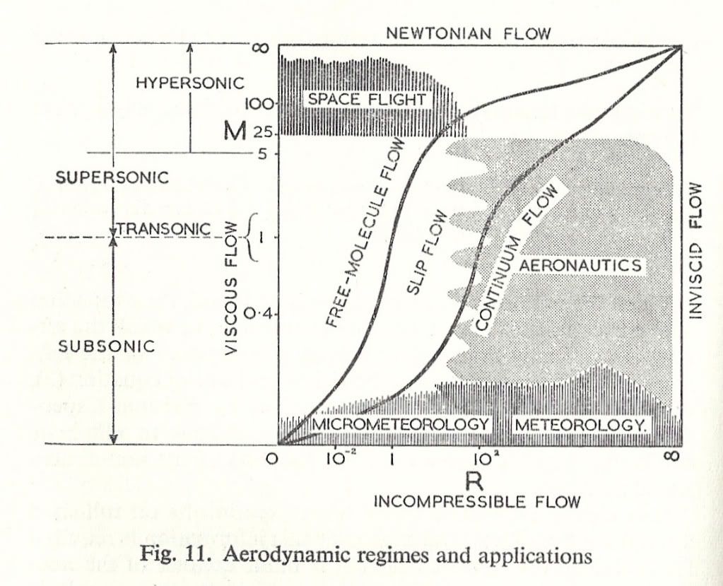
I have never heard of "slip" in this context. I understand vaguely what Reynold's numbers mean in that it's a function of scale.
Which would be?
yes, according to those prior excerpts; however shock wvae pattern at those speeds are remarkably complex, and also due to very high altitudes the effect of 'slip' a Reynold's number effect-in the manner in which the boundary layer 'slips' relative to the wing this also changes lift characteristics and the overall L/D ratio ,lift-slope curve, pitching moments coefficient, etc...
in short the exact plan form configuration chosen by the designers is contingent upon numerous factors,...but lowered total drag may simply not be that important on a particular design compared with other aspects of the design...
I understand vaguely what Reynold's numbers mean in that it's a function of scale.
Reynolds Number
Which would be?
, stability problems, structural efficiency, volumetric space for fuel and auxiliaries...etc...
Thread Starter
Join Date: Dec 2010
Location: New York & California
Posts: 414
Likes: 0
Received 0 Likes
on
0 Posts
Pugilistic Animus
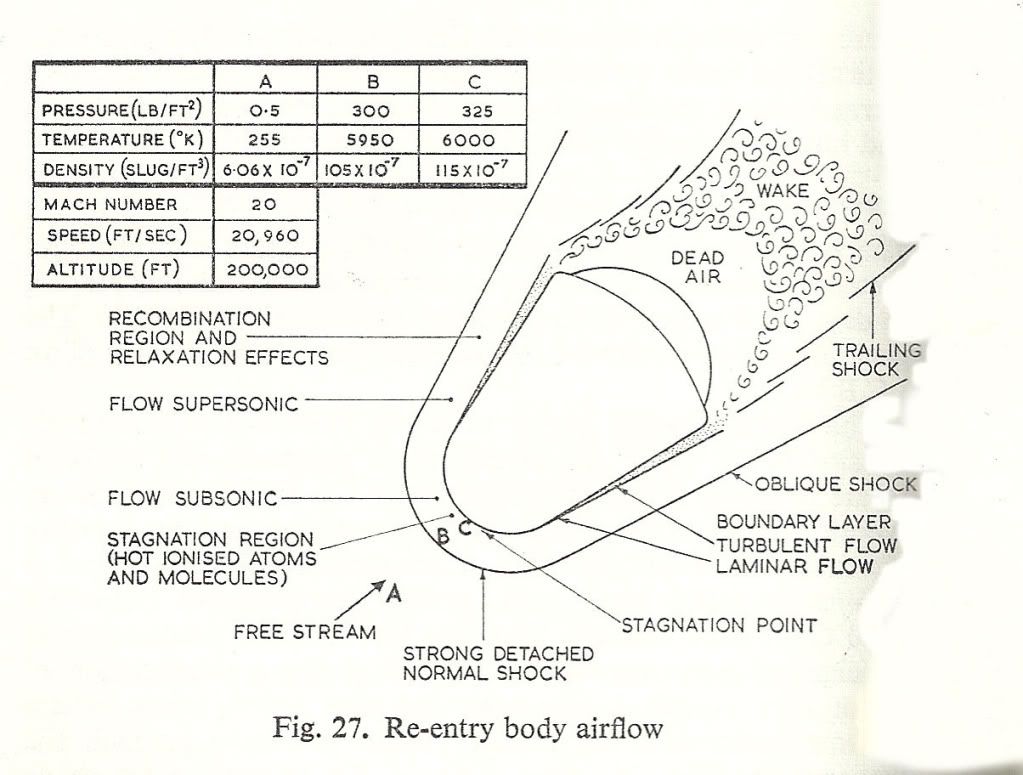
Just a brief glance at the page it looks almost like higher reynolds numbers would lead to the airflow at the stagnation points taking longer as you go rearwards to "de-stagnify" and go back up to normal speeds. A lot of turbulence I'm sure would ensue as well.
You mean hot spots on the plane?
How would that occur? High pressure zones occurring in key areas due to the airflow stagnating and not accelerating back up?
Well, that makes more sense as delta wings are very strong structures
Makes sense as many hypersonic concepts use low density fuels.
Still, I thought the whole purpose of a wave-rider is to produce an aircraft that can get high L/D ratios while at high mach (where it is harder to do so)
have a look at this...
thermal transfer problems..
stability problems
structural efficiency
volumetric space for fuel and auxiliaries...etc...
Still, I thought the whole purpose of a wave-rider is to produce an aircraft that can get high L/D ratios while at high mach (where it is harder to do so)
Just a brief glance at the page it looks almost like higher reynolds numbers would lead to the airflow at the stagnation points taking longer as you go rearwards to "de-stagnify" and go back up to normal speeds. A lot of turbulence I'm sure would ensue as well.
all of these items are very very difficult to predict with theory due to slip, when speaking about very high speed flight at the usual very high altitudes....Reynold's number effect and Mach number effects are intertwined in a horribly complex way...
How would that occur? High pressure zones occurring in key areas due to the airflow stagnating and not accelerating back up?
at very very high altitudes the mean free path of the air molecules at a constant Mach or a constant dynamic pressure may exceed the span by such a factor that the boundary layer moves, continuity is lost because the boundary layer is no longer in a steady state flow respective to the wing section......slipping with the wing....even as of today theoretical treatment alone fails to make good predictions of laminar and turbulent separation points and shear effect skin friction coefficients when there is 'slip' ... not a stationary boundary layer as the theoretical treatments propose...and just as a reminder when comparing different forms it is important [due to the scale effects you mentioned] to always compare different sections and planforms at the same Rn and Mach number...otherwise the results are nonsense...
You mean hot spots on the plane?
Still, I thought the whole purpose of a wave-rider is to produce an aircraft that can get high L/D ratios while at high mach (where it is harder to do so)
Still, I thought the whole purpose of a wave-rider is to produce an aircraft that can get high L/D ratios while at high mach (where it is harder to do so)
Robyn Just like Puerto Ricans the designers have their 'reasons'...
I think you would have been great on a design team back in the 50's or early 60's...
Last edited by Pugilistic Animus; 7th May 2011 at 22:15. Reason: more coherent--I think
Thread Starter
Join Date: Dec 2010
Location: New York & California
Posts: 414
Likes: 0
Received 0 Likes
on
0 Posts
Pugilistic Animus

I drew this up. The sweep angles and stuff aren't absolute but the idea is that it has almost no sweep in the middle similar to a spatular section and progressively sweeps more and more as you go outboard. Ogival.
Can you give a simple explanation of what wetted area is?
The skin friction drag I understand -- higher reynolds numbers would mean more turbulent flow (I'm guessing stronger shockwaves, more heat produced).
The pitching moment co-efficient, is that due to high pressure spots formed on parts of the fuselage monkeying around with the center of pressure?
When you say the boundary layer slips? Do you mean that from the stagnation point the flow speeds back up at a slower rate than normal, and/or that the lower area of the flow accelerates up speed unusually slow compared to the upper layers?
I'm sure that I'm being very simplistic overall, but as a rule of thumb I generally learn best by grasping the basic concept first and then proceeding from there.
Gotta see and test it...
I drew this up. The sweep angles and stuff aren't absolute but the idea is that it has almost no sweep in the middle similar to a spatular section and progressively sweeps more and more as you go outboard. Ogival.
yes, it has do do the volume/wetted area-ratio one need a large value to go faster, because the geometric volume increase must be higher than than wetted area increase...as measure of effective lift...
well despite the mechanistic reasons, from continuity and conservation of energy and momentum, for either laminar and turbulent flow separation...Flow separation points are very important to attempt to predict, but because of Reynold's number effects, prediction of such terms as the skin friction drag and pitching moment coefficient.
The pitching moment co-efficient, is that due to high pressure spots formed on parts of the fuselage monkeying around with the center of pressure?
all of these items are very very difficult to predict with theory due to slip, when speaking about very high speed flight at the usual very high altitudes....
I'm sure that I'm being very simplistic overall, but as a rule of thumb I generally learn best by grasping the basic concept first and then proceeding from there.
my stupid power cord pulled out, while posting earlier, I hate typing so I'll just be brief...and I'll get back to the finer points later...
C
the amount of wing area immersed in effective [lift producing] flow at a given alpha
almost changes in pressure distribution due to flow separation point shifting, at different values of mach
not necessarily, stronger shock waves just very complex shock wave interactions...most of temperature rise is due to compression of the air, although frictional heating term is important too
it's more of a conceptual term, meaning the boundary layer fails to separate at points predicted assuming a constant 'flow rate'...by an amount 'eta' that eta is the coefficient of slip ---it really can't by theoretically computed---it's due to the long paths over which the air molecules must travel...
I can see how something like that would cut through and ride the waves---surfboard-like....and also a decent amount of area for the low speed regimes of takeoff and landing....I can't really say how it would do,...but you could probably get an airplane out of it---that's actually how it all really starts even the SR-71, Concorde, B757 etc...imagination 
me too...
C
an you give a simple explanation of what wetted area is?
The pitching moment co-efficient, is that due to high pressure spots formed on parts of the fuselage monkeying around with the center of pressure?
The skin friction drag I understand -- higher reynolds numbers would mean more turbulent flow (I'm guessing stronger shockwaves, more heat produced).
When you say the boundary layer slips? Do you mean that from the stagnation point the flow speeds back up at a slower rate than normal, and/or that the lower area of the flow accelerates up speed unusually slow compared to the upper layers?
I drew this up. The sweep angles and stuff aren't absolute but the idea is that it has almost no sweep in the middle similar to a spatular section and progressively sweeps more and more as you go outboard. Ogival.
I'm sure that I'm being very simplistic overall, but as a rule of thumb I generally learn best by grasping the basic concept first and then proceeding from there.
Thread Starter
Join Date: Dec 2010
Location: New York & California
Posts: 414
Likes: 0
Received 0 Likes
on
0 Posts
Pugilistic Animus
Understood
So basically the surface area of the upper and lower surfaces of the wings/fuselage and so forth not counting volume inside them? Does this factor the curves of the wing's top and bottom surfaces and the curves of the fuselage and so forth?
And pressure distributions ultimately yields center of pressure shifts
You mean interference effects?
(I was always under the impression that higher reynolds numbers meant more turbulence though)
I understand
Does it separate more towards the front of the wing/fuselage, or more towards the rear of the wing/fuselage as the reynolds numbers go up?
Wait... if it can't be theoretically computed, then how come people were able to design objects that fly at hypersonic speed?
I didn't think of it that way, but I suppose it does look a little bit like the front of a surfboard
Understood
True enough
my stupid power cord pulled out, while posting earlier, I hate typing so I'll just be brief...and I'll get back to the finer points later...
the amount of wing area immersed in effective [lift producing] flow at a given alpha
almost changes in pressure distribution due to flow separation point shifting, at different values of mach
not necessarily, stronger shock waves just very complex shock wave interactions...
(I was always under the impression that higher reynolds numbers meant more turbulence though)
most of temperature rise is due to compression of the air, although frictional heating term is important too
it's more of a conceptual term, meaning the boundary layer fails to separate at points predicted assuming a constant 'flow rate'...
by an amount 'eta' that eta is the coefficient of slip ---it really can't by theoretically computed---it's due to the long paths over which the air molecules must travel...
I can see how something like that would cut through and ride the waves---surfboard-like....
and also a decent amount of area for the low speed regimes of takeoff and landing....I can't really say how it would do,...but you could probably get an airplane out of it
that's actually how it all really starts even the SR-71, Concorde, B757 etc...imagination
So basically the surface area of the upper and lower surfaces of the wings/fuselage and so forth not counting volume inside them? Does this factor the curves of the wing's top and bottom surfaces and the curves of the fuselage and so forth?
I'm not entirely sure what you mean here; ... picture shooting a water hose at the wing head on - a good portion of the wing will have a steady stream flowing over it and however the back section of the wing may only catch droplets of water due to dispersion as you angle the wing up then more of the wing will catch the droplets...not entirely correct as an aerodynamic analogy though...
Wait... if it can't be theoretically computed, then how come people were able to design objects that fly at hypersonic speed?
You mean interference effects?
(I was always under the impression that higher reynolds numbers meant more turbulence though)
(I was always under the impression that higher reynolds numbers meant more turbulence though)
...more turbulence =more math chaos
Does it separate more towards the front of the wing/fuselage, or more towards the rear of the wing/fuselage as the reynolds numbers go up?
Last edited by Pugilistic Animus; 13th May 2011 at 20:06.
Thread Starter
Join Date: Dec 2010
Location: New York & California
Posts: 414
Likes: 0
Received 0 Likes
on
0 Posts
Pugilistic Animus
I understand what you're trying to say.
Yes, but there are theoretical rules of thumb to take into account scaling differences right?
Okay
What's an adverse pressure ratio?
And what's shear drag?
I'm not entirely sure what you mean here; ... picture shooting a water hose at the wing head on - a good portion of the wing will have a steady stream flowing over it and however the back section of the wing may only catch droplets of water due to dispersion as you angle the wing up then more of the wing will catch the droplets...not entirely correct as an aerodynamic analogy though...
All Designs teams have designed planes w/o a full theoretical/computational analysis...there's always a difference between computed and actual flight characteristics...the base equations are themselves inexact...
Yes,...
...more turbulence =more math chaos
...more turbulence =more math chaos
low Rn numbers generally mean poor lift and drag characteristics... due to the laminar transition to turbulent against an adverse pressure ratio...
flow separation may be delayed in at low Rn but the shear-effect drag is more pronounced.
Guest
Posts: n/a
To have a "wing" at all whilst hypersonic begs the question. Do we need a wing at all ?? Save for down low, and transition back from Bullet to Truck ??
variable geometry or retracting geometry??
The Valkyrie had a nifty feature that drooped her outer wing, moving a wing 90 degrees loses all drag due Lift, and we are left with parasite, retaining all cargo and systems volume.
bear
variable geometry or retracting geometry??
The Valkyrie had a nifty feature that drooped her outer wing, moving a wing 90 degrees loses all drag due Lift, and we are left with parasite, retaining all cargo and systems volume.
bear
Thread Starter
Join Date: Dec 2010
Location: New York & California
Posts: 414
Likes: 0
Received 0 Likes
on
0 Posts
bearfoil
The wing didn't fold down 90-degrees. The wing could be folded down 25-degrees or 64.5 degrees on A/V-1 (On A/V-2 it could be folded down 30-degrees and 69.5 degrees due to the aircraft having a 5-degree dihedral).
The Valkyrie had a nifty feature that drooped her outer wing, moving a wing 90 degrees loses all drag due Lift, and we are left with parasite, retaining all cargo and systems volume.