


EC135 Fan Fail

Thread Starter
Join Date: Aug 2008
Location: Little Rock, AR
Age: 58
Posts: 7
Likes: 0
Received 0 Likes
on
0 Posts
EC135 Fan Fail
On the EC135P2+, can anyone explain the "FAN FAIL" segment light below the engine control panel? Purpose and function? Any help and/or reference would be appreciated. Thanks in advance.

Avoid imitations
Join Date: Nov 2000
Location: Wandering the FIR and cyberspace often at highly unsociable times
Posts: 14,631
Received 513 Likes
on
273 Posts
I don't fly that type but on others I have flown, a similar caption refers to a cooling fan for the EFIS units.

Thread Starter
Join Date: Aug 2008
Location: Little Rock, AR
Age: 58
Posts: 7
Likes: 0
Received 0 Likes
on
0 Posts
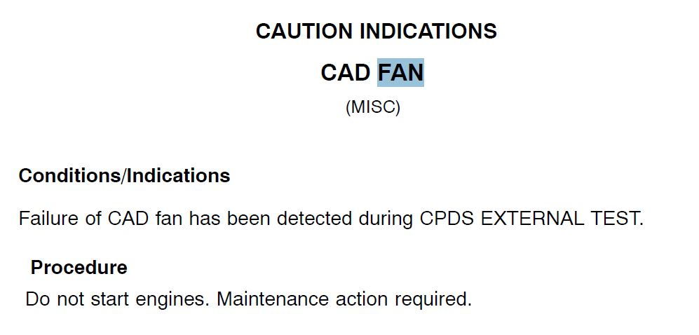
ShyTorque, Thanks for your reply. I tend to agree that it would have something to do with the Avionics/Displays in the dash. The EC135 has caution lights which will display on the Cautions/Advisory display "CAD FAN" and "VEMD FAN" along with a "FAN" indication that will display on the PFD and ND dealing with the FCDS, however, there is no mention in the RFM (including any flight manual supplements) or any Eurocopter manuals (at least the one's that I have) where I can find any specific mention of this particular "FAN FAIL' segment light. Strange.....One would think this would be listed somewhere in the EP or Limitations section of either the baseline RFM or FMS.

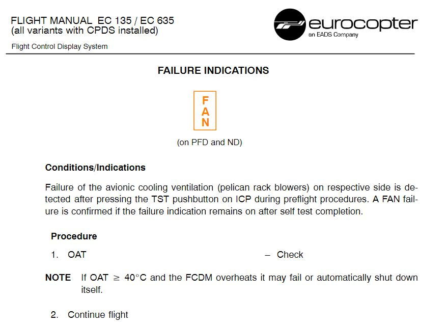
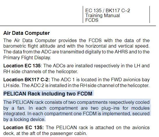
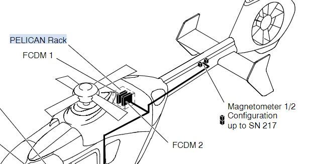
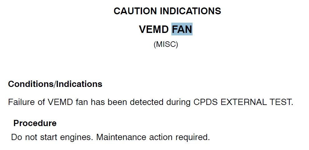
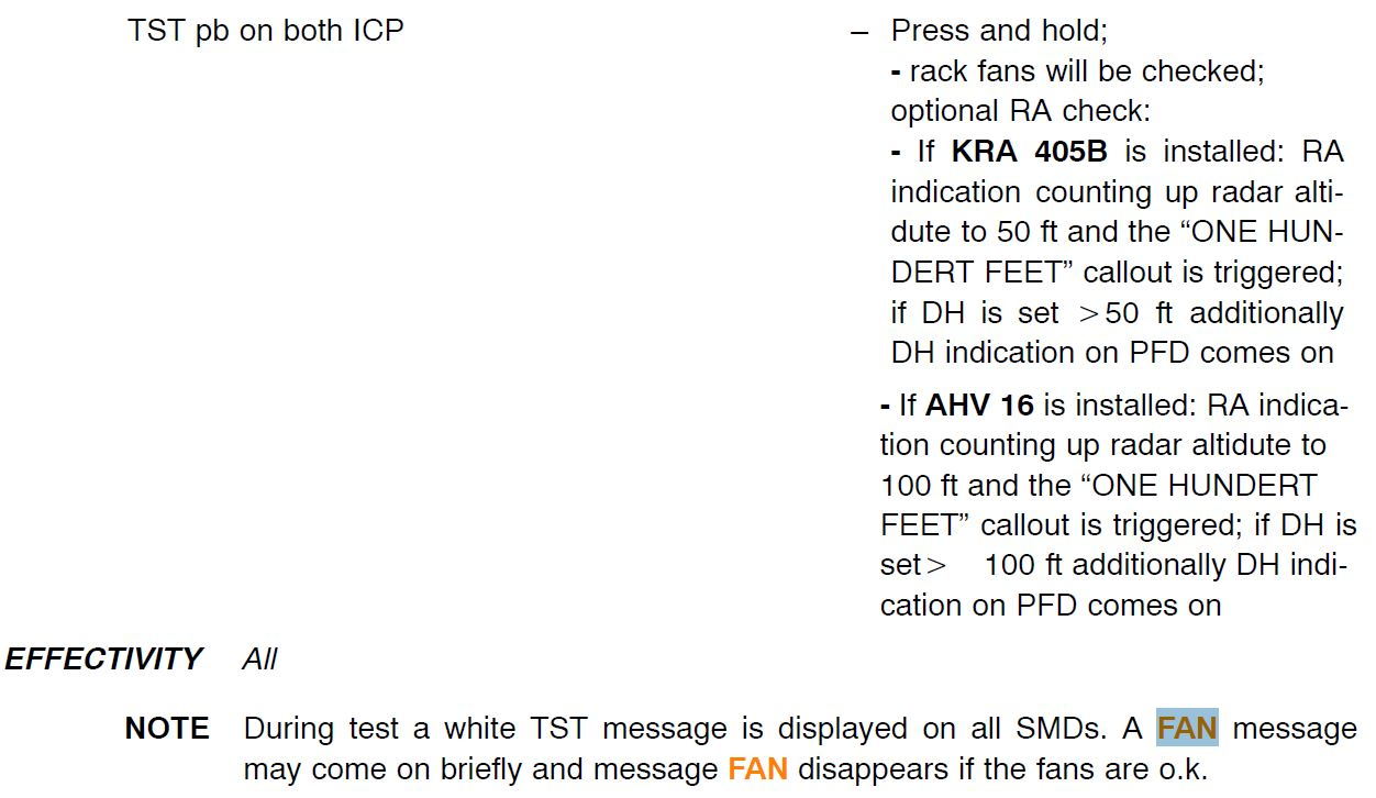
The light is not a component of the basic aircraft or covered in the basic P2+ RFM/FMS. My guess is it’s probably a component of an STC (Metro SPIFR kit perhaps?). Or is it installed on an aircraft with CDS panel? As shown above, the CPDS FAN failure warning is displayed on the PFD which refers to a failure of an avionics rack fan (see the RFM SUPPLEMENT FOR SINGLE/DUAL PILOT IFR OPERATION KIT).
Thread Starter
Join Date: Aug 2008
Location: Little Rock, AR
Age: 58
Posts: 7
Likes: 0
Received 0 Likes
on
0 Posts
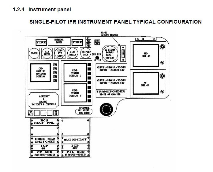
The "FAN FAIL" segment that I am referring to is a segment light below the Engine Control Panel (the one with the FADEC switches) next to the High NR switch. The "FAN" mentioned above is displayed on the PFD/ND dealing with the FCDS Pelican Racks. The "CAD FAN" and "VEMD FAN" caution messages are displayed on the CAD. Sorry I am unable to post a Pic as I have not been an active member long enough and PPRUNE indicates I have to make 10 posts before I can upload a Pic. Possibly a Metro Mod as mentioned above however it is pictured in all of the FSI manuals and FSI cockpit posters. Also installed in each of the aircraft I have seen/flown. Thank you all for your help! Maybe I am missing something but I have not been able to get the answer after searching many publications and inquiring many instructors.
More than likely a Metro mod as just about every 135 delivered in the US was completed by them rather than AHI.
Single Pilot IFR Avionics Installation Kit PN 135M-I50 and I35M-250 installed by Metro Aviation, Inc. in the ECI35 helicopter.
EQUIPMENT MAINTENANCE MANUAL
SINGLE PILOT IFR AVIONICS INSTALLATION
PART I SYSTEM DESCRIPTION
CHAPTER 23
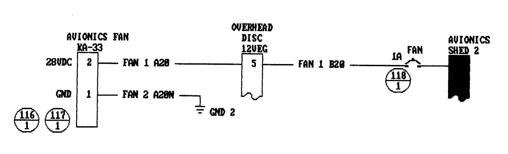
As a requirement for IFR the GPS system requires forced air cooling for the GPS/NAV/COM System.
A supplemental avionics fan is installed to provide this as well as for the transponder for added reliability.
EQUIPMENT MAINTENANCE MANUAL
SINGLE PILOT IFR AVIONICS INSTALLATION
PART I SYSTEM DESCRIPTION
CHAPTER 23
As a requirement for IFR the GPS system requires forced air cooling for the GPS/NAV/COM System.
A supplemental avionics fan is installed to provide this as well as for the transponder for added reliability.
Thanks RVDT.
The FSI simulator and documents reflect an actual serial numbered aircraft. It�s my belief that was a PHI P2+ with a Metro SPIFR modification. The RFM for the aircraft containing the �FAN FAIL� switch should incorporate the STC FMS with full explanation.
The FSI simulator and documents reflect an actual serial numbered aircraft. It�s my belief that was a PHI P2+ with a Metro SPIFR modification. The RFM for the aircraft containing the �FAN FAIL� switch should incorporate the STC FMS with full explanation.
Well, it's not for the SPIFR avionics fan. At least per the install drawing below. I seem to remember in previous 135 models there was an "overheat" light in that same position. It could be it is an Airbus temperature system that's been relabeled??? Perhaps a quick call/email to Metro will get your answer: https://www.metroaviation.com/contact/
Thread Starter
Join Date: Aug 2008
Location: Little Rock, AR
Age: 58
Posts: 7
Likes: 0
Received 0 Likes
on
0 Posts
Solved!
Thanks to everyone that replied and led me in the correct direction. I contacted Metro and it is indeed a part of their install. The air-condition STC to be exact. It is as mentioned above, related to an additional avionics cooling fan behind the instrument panel.
