


Alaska Airlines 737-900 MAX loses a door in-flight out of PDX

Join Date: Aug 2008
Location: Ithaca, NY
Posts: 5
Likes: 0
Received 0 Likes
on
0 Posts
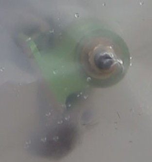
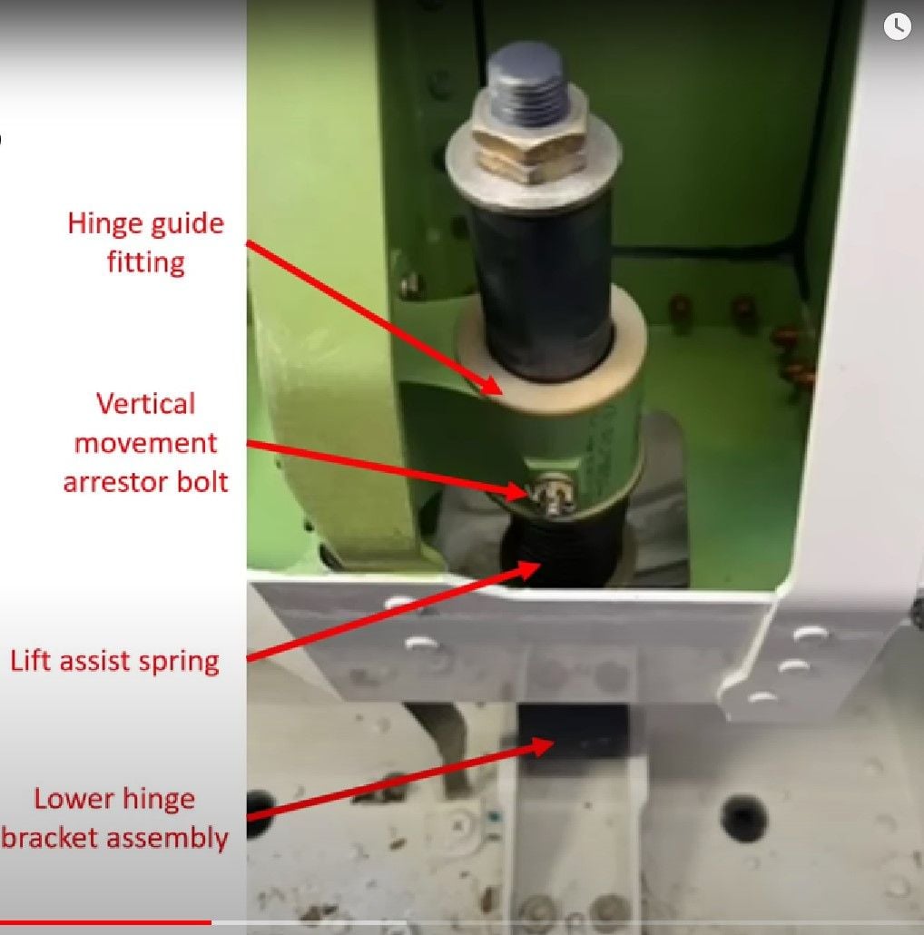
Looking at Mudman’s photos it can be seen that the rear hinge guide is at top of its travel with the lift assist spring fully extended. The face of the hinge guide which is at the top photo is the face which we can see on the previous United loose bolts photo. For my money there is no sign of the vertical movement arrestor / stop bolt which should be visible given the shape and colour of the castellated nut which should be there. If the bolt was not installed then that hinge assembly would have been exerting an asymmetrical upward force on the door. If the equivalent bolt was missing from the forward hinge then both would have been exerting an upward force.
Alternative views from anyone with better eyesight or imagination welcome.
Alternative views from anyone with better eyesight or imagination welcome.
Or am I likely completely off the mark here?


Join Date: Jan 2024
Location: Portland, OR
Posts: 1
Likes: 0
Received 0 Likes
on
0 Posts
Looking at Mudman’s photos it can be seen that the rear hinge guide is at top of its travel with the lift assist spring fully extended. The face of the hinge guide which is at the top photo is the face which we can see on the previous United loose bolts photo. For my money there is no sign of the vertical movement arrestor / stop bolt which should be visible given the shape and colour of the castellated nut which should be there. If the bolt was not installed then that hinge assembly would have been exerting an asymmetrical upward force on the door. If the equivalent bolt was missing from the forward hinge then both would have been exerting an upward force.
Alternative views from anyone with better eyesight or imagination welcome.
Alternative views from anyone with better eyesight or imagination welcome.
I would present a diagram of how this could have happened, but my account is still too new. Maybe later. Also, I am just guessing here, obviously there are several other possibilities.
Torque wrenches used in aviation need to be certified and tested on a regular basis. I remember seeing the serial number of a torque wrench recorded in the tech log after a job had been signed out.
Hopefully the paperwork trail will yield results.
Hopefully the paperwork trail will yield results.
737 Max Inspections Delayed as Boeing Revises Guidance
The Federal Aviation Administration said that Boeing’s instructions for how airlines should check the planes were insufficient and that the company would revise them.Join Date: Nov 2018
Location: VA
Posts: 30
Likes: 0
Received 0 Likes
on
0 Posts
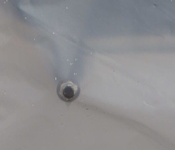
In Mudman's photos from NTSB (thanks to him by the way for discovering they had such resolution!), you see the ends of the folded-outward hinge shafts along with their bolts and washers. This is as if you were looking from the top down at the hinge/bracket assembly in an installed door plug. Position 2 has the hinge guide fitting (collar/bracket) with the hexagonal nuts at the end, Position 1 only has the shaft with its washer and hexagonal nuts at the end.
I've read a couple of hints above that USA practice might have more use of castellated nuts and split pins, compared to use of locknuts in other countries. In some practice, something with a split pin isn't necessarily tight, but might be floating, whereas it would be ordinary and locknuts that would more likely be done to a specific torque.
Join Date: Nov 2018
Location: VA
Posts: 30
Likes: 0
Received 0 Likes
on
0 Posts
Can be a pain in the ass, but in my experience 90% of the time the holes all line up at the low end torque. I work on helicopters, and 80% of the hardware is split pinned.
Edit to add.... also most of the hardware I have used, especially for flight controls, etc, the nuts are castellated and also have nylon self locking feature.
Example: https://www.aircraftspruce.com/catal...es/ms17825.php
Join Date: Feb 2022
Location: Canberra
Posts: 6
Likes: 0
Received 0 Likes
on
0 Posts
Join Date: Feb 2010
Location: abu dhabi
Posts: 3
Likes: 0
Received 0 Likes
on
0 Posts
I was wrong about the locking pin (Vertical Movement Arrestor Bolt) still being in place, after seeing better images I agree that the it appears gone and the Hinge Guide Fitting is stopped by the end plate of the Hinge Shaft, thanks to DaveReidUK and lateott for clarifying this (and also good picture with terminology).
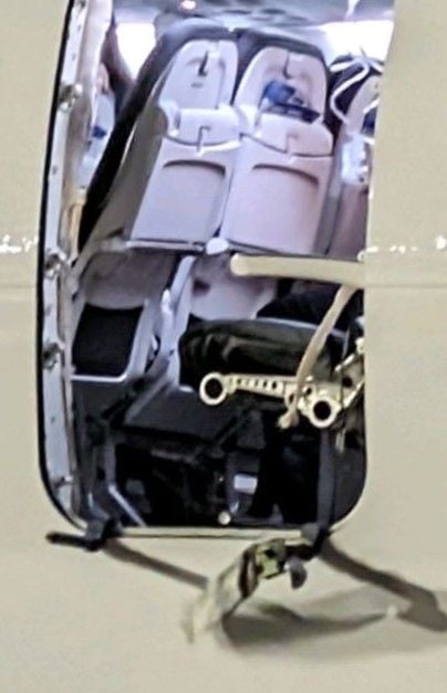
However, my main point is the important fact that the Hinge Guide Fitting (HGF) is not attached to the door frame, and that it appears undamaged at the attachments. Furthermore, this exact problem was found on one of the inspected United aircraft.
See sketch below to illustrate this point. If the HGF is loose from the door frame, that will allow vertical movement of the door regardless of whether all the other bolts are in place or not.
Last edited by mexmike; 10th Jan 2024 at 01:07. Reason: Nuts
Green Bits
Looking at the first photograph, the Green Bit is part of the door, not the frame of the aircraft. It must have been ripped from the door by aerodynamic forces, and by the explosive decompression. So was the last item to fail in the sequence.
The failure would have been initiated by the top rail locating mechanism, where it seems more than likely that the restraining bolts went missing, or were never installed in the first place.
The failure would have been initiated by the top rail locating mechanism, where it seems more than likely that the restraining bolts went missing, or were never installed in the first place.
On the topic of torque - the bolts holding the brackets in place should have been installed with and retained by prevailing torque nuts, the fancy name for locking nuts. The low grade version uses a nylon insert to grip the bolt. The better ones squash the nut to provide a springy grip. Either way, these do not spin loose the way conventional nuts do when the bolt looses tension. For the amount of gap seen in the United photos to happen means that the bolts and nuts were never completely tight.
A problem that is not common, but recognized, is that assemblers can put the nut in place by hand until it gets resistance from the locking feature and becomes too difficult to advance by hand and then is distracted and fails to use any wrench to finish the job. The nut continues to retain the bolt; it won't fall off, but it doesn't supply a clamp load to the joint. Since the resistance happens within only the first turn or two of engagement, the joint will have a greatly reduced capacity in tension. One might expect if a load is applied and the threads pull through that the related parts will be nearly undamaged.
In other words - it may not have been lack of knowing the torque - it was lack of using any wrench at all. That all of them in the United image are loose fits with distraction as a cause.
Lockwashers of any kind have been found to be essentially garbage for retaining bolts. If the tension of the bolt/nut relaxes even a little, the ability to "dig" in is eliminated and the lockwasher no longer participates. A more complete description is on boltscience.com , with many, many pages, but in an approachable and informative manner.
Lock nuts, prevailing torque features, locking compound, lock wire, and cotter pins are all useful to ensure the fasteners do not become separated items, though they cannot alone ensure that tension remains in the bolt/screw to clamp the related parts. Lockwire and locking compound do have a bit of advantage in that the assembler needs to be committed to using them and therefore act as an indicator, though not a guarantee, that the assembler provided the correct torque.
Cotter pins are useful when a joint that requires a nut to be in position but not providing a clamp load. For example - a nut on wheel bearings needs to leave a small amount of clearance for the bearing to work correctly (not crushing the balls or rollers) but also cannot be allowed to move. This is appropriate for the guide roller capture bolts - to not crush the gap and trap the roller, but also not work loose.
That one guide remained on the hinge doesn't surprise me. There would be considerable force acting on those small fasteners with a large lever arm.
Boeing CEO now stating that the company must “acknowledge our mistake” and address the issue with “100% transparency.” What mistake is Calhoun acknowledging? He doesn’t say. That doesn’t sound like 100% transparency. If he knows it was a Boeing production error, he should so state and identify when and how the “mistake” occurred. I suspect Boeing GC has a firm grasp of Calhoun’s short hairs.
I’m confident that 99.98% of Boeings employees had nothing to do with the ASA 1282 accident. Being tarred with “our mistake” is not a morale booster for the rank and file.
I’m confident that 99.98% of Boeings employees had nothing to do with the ASA 1282 accident. Being tarred with “our mistake” is not a morale booster for the rank and file.
How do you use a torgue wrench with a nut which requires a split pin afterwards?
I've read a couple of hints above that USA practice might have more use of castellated nuts and split pins, compared to use of locknuts in other countries. In some practice, something with a split pin isn't necessarily tight, but might be floating, whereas it would be ordinary and locknuts that would more likely be done to a specific torque.
I've read a couple of hints above that USA practice might have more use of castellated nuts and split pins, compared to use of locknuts in other countries. In some practice, something with a split pin isn't necessarily tight, but might be floating, whereas it would be ordinary and locknuts that would more likely be done to a specific torque.
Join Date: Mar 2016
Location: San Diego
Posts: 4
Likes: 0
Received 0 Likes
on
0 Posts
I was wrong about the locking pin (Vertical Movement Arrestor Bolt) still being in place, after seeing better images I agree that the it appears gone and the Hinge Guide Fitting is stopped by the end plate of the Hinge Shaft, thanks to DaveReidUK and lateott for clarifying this (and also good picture with terminology).
However, my main point is the important fact that the Hinge Guide Fitting (HGF) is not attached to the door frame, and that it appears undamaged at the attachments. Furthermore, this exact problem was found on one of the inspected United aircraft.
See sketch below to illustrate this point. If the HGF is loose from the door frame, that will allow vertical movement of the door regardless of whether all the other bolts are in place or not.
One of the hinge brackets is still on the plane, the other is missing. In an earlier photo it wasn't clear but the newest photo shows that the bracket is absent on both sides on the door. For this reason, the NTSB asked in the press conference to look out for a green thing.
Every wheel I've fitted on a big jet uses a castellated nut on the axle. This is torque loaded twice, once to bed in the wheel bearings, then backed off and torque tightened again. There is usually a range, say 150-170 lb/ft. Start low and work up until the holes line up. Admittedly it's not a split pin that goes through, usually it's two bolts 180° apart which are of course locked with castellated nuts and split pins. Again (cough) torque tightened to the specified figure.
Next question. Why are emergency exits plugged at all; given that Boeing and airlines insist that safety is paramount. Recent JAL accident should remind us that too many exits are not enough. Forty years ago aviation professionals were outraged when British Airways deactivated two of the eight exits on main deck of their B747s. BA had a fairly spacious cabin and could legally dispense with the doors but it seemed wrong to deliberately downgrade safety. Eventually regulations were changed in 1990 to require no more than 60 feet between exits. But BA kept their layout and commercial advantage. Why no similar outcry about plugs on the MAX 9 and predecessor?
Join Date: Jul 2015
Location: YVR
Posts: 63
Likes: 0
Received 0 Likes
on
0 Posts
I personally thought it was looking like bolts were omitted altogether. However, multiple findings of loose bolts on multiple aircraft on both AS & UA would change that opinion. I saw somewhere (from Jon Ostrower maybe?) that there was a 11 month age different between the UA frames in question, so it's not like they are consecutive airframes. That would point to a systematic failure in manufacturing processes. The question is, at Spirit of Boeing? I understand the bare airframe arrives from Spirit at Renton with plug installed, good to go. The question is if Boeing remove it at any time.
To rule out any bad batch of bolts, nuts or pins - bad thread or something. Does anyone know if the bolts in question are exclusively used on these plugs, or are they fairly generic and used for other applications throughout the aircraft - including in the -8?
I was also trying to find out about the wiring. If it were a door, there would be sensors with corresponding wiring to send a message to the cockpit if there was any issue like all the other doors. I understand the airframe arrives from Spirit as an empty shell and Boeing install all wiring. In the case of a plug, would Boeing a) install these sensors anyway and just not connect them b) just install the wiring in case the sensors are added later or c) there is no door wiring at all and it would all be added at time of conversion from plug to door should it happen? In the case of c) which I believe is the correct option, I guess there is no particular reason for Boeing to look at the hardware of the plug in any way, but if a) or b) then I guess Boeing are 100% taking the thing in and out.
I also have a question about the seal, does anyone have a picture of it? Is it merely for insulation, or does it have a greater purpose? I understand there should be zero draft able to be felt in the cabin at all from around a plug as it is completely airtight, cabin insulation not withstanding. Is that correct? Ie if there was a draft it should have been picked up.
One final question, would plugs need to be removed for exterior painting?
Next question. Why are emergency exits plugged at all; given that Boeing and airlines insist that safety is paramount. Recent JAL accident should remind us that too many exits are not enough. Forty years ago aviation professionals were outraged when British Airways deactivated two of the eight exits on main deck of their B747s. BA had a fairly spacious cabin and could legally dispense with the doors but it seemed wrong to deliberately downgrade safety. Eventually regulations were changed in 1990 to require no more than 60 feet between exits. But BA kept their layout and commercial advantage. Why no similar outcry about plugs on the MAX 9 and predecessor?
The number of operative doors/emerg exits satisfies the evacuation requirements of the regulator (FAA).
Above a certain passenger number (pretty sure i heard 205 mentioned) there is a requirement for those 2 mid cabin doors to be operative & fitted with emergency slides.